Dirtrider412
5+ Year Contributor
- 65
- 3
- Jan 7, 2018
-
Coraopolis,
Pennsylvania
Follow along with the video below to see how to install our site as a web app on your home screen.

Note: This feature currently requires accessing the site using the built-in Safari browser.

This site may earn a commission from merchant
affiliate links, including eBay, Amazon, and others.
This site may earn a commission from merchant affiliate links, including eBay, Amazon, and others.
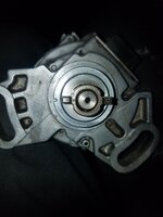
You must be logged in to view this image or video.Why is the notch and punch on the opposite sides. This one on google has them both on the same side. I wasnt lazy I'm getting conflicting information.
how do i go about testing it? i did the test stated above using the multi meter and never got 5 volts from pins 1 and two which are the Crank and Cas pins. ground pin 4 and hook a probe to the first two pins one at a time and just spin it and look for 5v?
It was strange the cas almost acted like a volume control I could slowly turn the tab and watch the voltage slowly climb a as I turned it then hit a peak then went back down as you turned it past a certain point.
Oh ic ok. Thanks man! You think 1v is enough to be out of range I can't find anything about the cas in my fsm
I took them out of the ecu pin connector and applied 12v to it and I had 12v at the other end.
When I turn the CAS by hand I don't hear any clicking from the injectors or anything and I haven't been getting any voltage reading from the TDC and cam signal.
Describe this in more detail. As written it doesn't establish that your CAS to ECU wiring is good.
As discussed, the CAS gets fed 12v and ground to power it and the other two wires are the signals for Crank and Cam positioning. The FSM shows that both of these have pullup's in the ECU to +5v. So with the CAS disconnected and the MPI relay activated you should measure 12v on the big red wire to pin 3, +5 on both the little black wire on pin 2 and the little white wire on pin 1, and 0v (ground) on the big black wire on pin 4). With the CAS and ECU disconnected you should have continuity between CAS pin 2 and ECU pin 21, continuity between CAS pin 1 and ECU pin 22, and no continuity between any of the 4 wires (checking that none are shorted to each other & ground or battery.)
If you don't have 12v on pin 3 or Ground on pin 4 the CAS isn't going to work.