The Top DSM Community on the Web

For 1990-1999 Mitsubishi Eclipse, Eagle Talon, Plymouth Laser, and Galant VR-4 Owners. Log in to remove most ads.

Please Support Morrison Fabrications
Please Support Rix Racing

2G Alternator Trigger Wire

This site may earn a commission from merchant
affiliate links, including eBay, Amazon, and others.

This site may earn a commission from merchant affiliate links, including eBay, Amazon, and others.

bettfootball

10+ Year Contributor
630
908
Mar 7, 2010
Edina, Minnesota
Hey guys.

I've been battling alternator problems for almost 10 years on my 99.

My problem I believe boils down to my inability to read wiring diagrams, or not having the correct ones maybe.

Basically, my alternators never charge until I rev the engine up to 3000rpm or so.

Leading me to believe this is a "trigger wire" that I have came across multiple threads on this site.

On my alternator harness, the blue wire is disconnected, and I have zero clue where this goes.

If anyone is good with wiring diagrams and can point me in the direction it would be GREATLY appreciated, I'm stumped.

I've had a dozen or so alternators in this thing, and I currently have an OEM alternator in it with the same problem.

Thanks for any help guys.

-Brady
 
I've gone rounds with my 2g alternator, it's basically pcm controlled.

If I remember correctly the pcm provides a ground to the alternator regulator which reduces voltage output to ~12.6v. It can apply the ground to the alternator regulator in a duty cycle manner which allows it to change the output as it see's fit.
Can't remember the colors because it's been a while but one wire is field feedback from the alternator to the pcm, the pcm then decides how much voltage to output based on engine loading I believe.
So at lower rpm higher load the alternator will ground out the terminal to reduce engine load or strobe/pulse it to maintain a certain alternator output.
One wire goes to the charge indicator light or I should say lack of charging indicator light.
I think the last wire is 12v.
You can clip the pcm wire to the regulator that allows the pcm to send a ground to the regulator letting the regulator provide full output however my experience was that the stock regulator does not control voltage output smoothly without the pcm. Plenty of output but the voltage fluctuates way too much, at least in my case.
 
You must be logged in to view this image or video.
 
Thank you!!! ^^^^ I have no idea what manuals I was looking at. I'm such a rookie when it comes to these so I couldnt' tell if I was looking at the right model year etc etc.

It seems the blue wire goes from ignition to the warning light, then to the alternator. This is the one that was cut or became damaged that I need to find in the harness and reconnect!

Thanks Guys.
 
Last edited:
The 2g turbo and 2g NT are completely different. If you have the 2g turbo with the 4 pin connector (red,blue,green,white wires), the blue goes to the charge (ie. battery) light on the dash and to a generator relay (which is just a backup to the dash charge light should that light not work - the generator relay is often destroyed or not even present on some years). The blue MUST be connected or alt won't work. The blue is sometimes shown as a black-yellow in the diagrams when you have a generator relay. Later years (like my 99) often don't have a generator relay and so you have a blue wire (even though a generator relay is shown in my 99 diagrams).
{The pcm controls the alt only on the NT.}
 
Last edited:
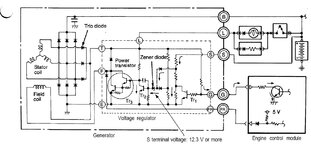
My 97 GST uses the PCM to control the alt voltage regulator by applying a duty cycle to the G terminal, it's in the schematics shown above.
You can disconnect the G terminal and the regulator will output full voltage until the regulator voltage limit is reached.
It's not just NT applications
The alternator regulator ultimately controls voltage from the alternator but the pcm uses the G terminal to apply a control to the regulator.
When the terminal receives a ground the alternator regulator reduces output voltage to 12.3 volts.
The "G" terminal on the 2g alt has a very unique special control purpose but it doesn't use a duty cycle from the ECU (see #3 below).

Points:
1) You have a 97 GST turbo which has an ECU, NOT a PCM. The PCM is in the 2g non turbo (see #2).

2) You mention the schematics shown above. Well look at them again - page 90-48 shows an ECM (Engine Control Module - aka ECU, Engine Control Unit which everyone everywhere refers to it as - {only Mitsubishi in their diagrams calls it a ECM, everyone else everywhere always calls it an ECU, even on DSMTuners and mechanics in shops, kind of a default industry standard terminology}). The PCM (Powertrain Control Module) is on the Non-turbo on page 90-46 (which he didn't show but I can produce if you need).

3) The "G" terminal is a special control line from the ECU which when grounded (held low when ECU output transistor is turned on) forces the max output voltage of the alt to 12.5V maximum. This is used temporarily under heavy engine load conditions (eg. full throttle with a lot of electrical loads) to put more power to the wheels by using less to drive the alt (power needed to drive the alt belt). So it purposely temporarily sacrifices electrical output to give more power to the wheels for the short time it's needed (like full acceleration when high electrical loads are active). It does not use a duty cycle but rather is toggled by the ECU when extra power is needed.

4) The "G" terminal is normally floating high (or disconnected if you will, via ECU output transistor turned off) when the ECU is not using it's special function. The alt then performs normal voltage regulation.
 
Last edited:
Dont know if it matters, but the diagrams i posted are out of the 99 FSM except the wiring diagram, its out of the 98 FSM.
 
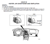
i think your forgetting about the cool air bypass lever :D
 

Attachments

  • upload_2018-11-7_6-11-50.png
    upload_2018-11-7_6-11-50.png
    43.1 KB · Views: 1,091
The 2g turbo and 2g NT are completely different. If you have the 2g turbo with the 4 pin connector (red,blue,green,white wires), the blue goes to the charge (ie. battery) light on the dash and to a generator relay (which is just a backup to the dash charge light should that light not work - the generator relay is often destroyed or not even present on some years). The blue MUST be connected or alt won't work. The blue is sometimes shown as a black-yellow in the diagrams when you have a generator relay. Later years (like my 99) often don't have a generator relay and so you have a blue wire (even though a generator relay is shown in my 99 diagrams).
{The pcm controls the alt only on the NT.}

Hold on a sec.. are you telling me that I need to do something differently? It is a 99 engine harness with the 4 pin connector, my blue wire seemed to be cut/damaged, either way it is not connnected to anything. Alternator *charges* albeit poorly and only if i rev up above 3k first.

-Brady
 
ECM, ECU, PCM, it's semantics, anybody around cars can figure out what was implied...

G is duty cycle controlled by the "ECM"...

I thought my alt was going bad since the voltage would drop to battery voltage at idle, after seeing the same thing after replacing I found out it was the "ECM" limiting output via the G terminal.

So to get rid of the ECM's control of the regulator I disconnected G & FR which allowed the alternator voltage regulator to fully control output without the ECM.

Cutting FR set a ECM code PXXX, the ECM checks for field power from the alternator

With G & FR cut voltage output would easily hit 14.4v however it would also hit 15v then drop to 14v which causes the lights to shine bright then dim and brighten and dim. The mitsu regulator does not maintain a nice steady output in my case.

Reconnected the G & FR and voltage is maintained by the ECM at 13.x volts during normal driving and drops to 12.6v at idle.
 

Attachments

  • 2galt.jpg
    2galt.jpg
    111.6 KB · Views: 1,437
  • 2galt2.png
    2galt2.png
    88.3 KB · Views: 270
Last edited:
Hold on a sec.. are you telling me that I need to do something differently? It is a 99 engine harness with the 4 pin connector, my blue wire seemed to be cut/damaged, either way it is not connnected to anything. Alternator *charges* albeit poorly and only if i rev up above 3k first.

-Brady

Download the 2g Technical Information and Troubleshooting Manual courtesy of Twicks69 from the tech archives, it explains the theory of operation for the charging circuit starting at page 91 (1-70), how it is controlled & what wire goes where.
 
Hold on a sec.. are you telling me that I need to do something differently? It is a 99 engine harness with the 4 pin connector, my blue wire seemed to be cut/damaged, either way it is not connnected to anything. Alternator *charges* albeit poorly and only if i rev up above 3k first.

-Brady
No, nothing differently. You need to reconnect the alt 4 pin connector blue wire back up. It ends up going to the dash charge (battery) light on the light's negative side. This light MUST be working for the alt to put out. Also make sure the alt 4 pin connector red wire is connected. It is a voltage sense wire that goes to battery positive that the alt needs.

Just FYI only: On your initial post you didn't say whether you had a turbo or NT. The alts are completely different and both have a blue wire. On the turbo (which I now know you have) there is a 4 pin connector and the alt has it's own regulator inside and the engine computer is an ECU (or ECM as Mitsu calls it). On the NT there is only a 2 pin connector and the alt does not have it's own regulator inside. The engine computer is called a PCM and it controls the alt's regulation via that 2 pin connector.

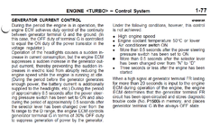
Stillrunning: I'm not trying to berate you with semantics. Yes an ECM, ECU, PCM, are all engine computers. And ECM and ECU are used interchangeably to refer the same computer used with a Mitsubishi 2.0 turbo (and 2.4L) engine and alt (this alt has it's own regulator). However the PCM is very different in that it controls the alts regulation and is used in the Chrylser 2.0 NT engine and alt (this alt doesn't have it's own regulator) which is in the 2g Mitsubishi NT. So that's why I mentioned this in post 6 since at that time I didn't know which engine he had. Please don't take offense. BTW I've always had the 2g Tech Manual but apparently didn't read far enough to get to the alt operation described on page 1-77 as in your attachment in post 13. I stopped at page 1-76 when it started talking about Cooling Fan Control. Thanks for the update.
 
Last edited:
Support Vendors who Support the DSM Community
Boosted Fabrication ECM Tuning ExtremePSI Fuel Injector Clinic Innovation Products Jacks Transmissions JNZ Tuning Kiggly Racing Morrison Fabrications MyMitsubishiStore.com RixRacing RockAuto RTM Racing STM Tuned

Latest posts

Build Thread Updates

Vendor Updates

Latest Classifieds

Back
Top